Unit 1: Exploring the Nature of Light Phenomena
V. Developing Mathematical Representations of Pinhole Phenomena
Pinhole phenomena can provide useful tools in estimating quantities that are otherwise hard to measure. To do so, we need to develop ways to represent pinhole phenomena mathematically, both geometrically and algebraically.
A. Representing pinhole phenomena geometrically
The visual display provided by a ray diagram suggests describing pinhole phenomena geometrically. First we simplify the diagram, next name and label angles, and then interpret geometric aspects of two triangles evident in the refined ray diagram.
Question 1.14 How can you describe pinhole phenomena geometrically?
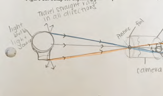
The ray diagram in Fig. 1.14 includes realistic sketches of the light bulb, the upside-down projection, and the pinhole camera as well as lines representing light rays inferred to be leaving the source and traveling straight through the pinhole to the screen.
This realistic portrayal of what we can actually see (the light bulb, camera, and projection on the screen) was helpful in using our conceptual model for light in explaining the upside-down projection of the light bulb observed on the screen: We could infer that light was leaving points on this source in many directions and envision that some light rays were traveling in straight lines:
- from the top of the light bulb straight through the pinhole to form the projection of the top of the light bulb near the bottom of the screen,
- from the middle of the bulb traveling straight through the pinhole to form the projection of the middle of the light bulb near the middle of the screen, and
- from the bottom of the bulb traveling straight through the pinhole to form the projection of the bottom of the light bulb near the top of the screen.
A more abstract stylized ray diagram, however, can focus attention on the envisioned light rays without the details of source, camera, and screen as shown in Fig. 1.17:
- Instead of a drawing of a light bulb, a vertical line represents the light source.
- Instead of a drawing of an upside-down projection of the light bulb on the screen, a parallel shorter vertical line represents this projection.
- Instead of an open circle, the pinhole is represented by an opening between short vertical lines above and below the point where the lines representing envisioned light rays cross. These short vertical lines represent the opaque end of the camera through which a pin was pushed to make the pinhole
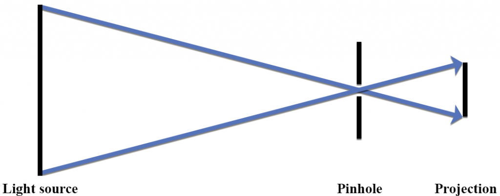
In Fig. 1.17, vertical black parallel lines represent the source and projection rather than sketches of the bulb and upside down projection. An opening between two small black vertical lines represents the open pinhole. The blue straight lines represent rays of light inferred to be traveling from the top and bottom of the bulb to the bottom and top of the screen where they form the upside down projection of the light bulb. The rest of the details of the source and the camera are not shown. The description of what is happening is the same:
- We are envisioning rays of light from the top of the vertical line representing the light bulb traveling straight through the opening representing the pinhole to form the projection of the top of the light bulb near the bottom of the screen.
- We are envisioning rays of light from the bottom of the light bulb traveling straight through the opening representing the pinhole to form a projection of the bottom of the light bulb near the top of the screen.
By using straight parallel vertical lines to represent the source and the projection, Fig. 1.17 simplifies the ray diagram so that two triangles become evident.
- What do these two triangles represent?
- How are these two triangles related?
One way to describe a ray diagram geometrically is to begin by naming the vertices of the triangles. In Fig. 1.18 for example, the vertices of the triangle on the left are labeled A, B, C, whereas the vertices of the triangle on the right are labeled F, E, C. (Later the letter D will represent the distance between line AB and vertex C, so D is omitted in naming vertices here.)
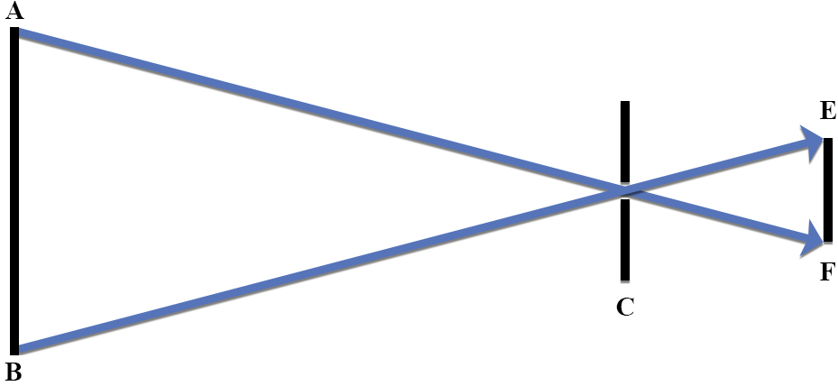
- How are the angles in these triangles related?
- What does it mean, for example, for two angles to be corresponding?
Which angle in triangle FCE corresponds to Angle A in triangle ACB?
Which angle in triangle FCE corresponds to Angle B in triangle ACB?
Which angle in triangle FCE corresponds to Angle C in triangle ACB? - What does it mean for two angles to be congruent?
- When are two angles congruent if formed by intersecting lines?
- What does it mean, for example, for two angles to be corresponding?
Triangles with three congruent corresponding angles are called similar triangles.
- Are triangles ACB and FCE similar triangles? If so, which are the three congruent corresponding angles?
- If triangles ACB and FCE are similar triangles, how are corresponding lengths related?
If you need to learn about similar triangles, see www.mathopenref.com/similartriangles.html and http://www.mathopenref.com/similartrianglesparts.html
For information about vertical angles, see http://www.mathopenref.com/anglesvertical.html
For information about congruent angles created by parallel lines and a transversal (sometimes called alternate interior angles), see http://www.mathopenref.com/anglesalternateinterior.html
Complete writing your own response to Question 1.14 before reading an example of student work and some nuances in representing pinhole phenomena geometrically.
1. Example of student work representing pinhole phenomena geometrically
A student drew the ray diagram in Figure 1.19 at the close of a class session in which the students developed and then used mathematical representations of pinhole phenomena to estimate a quantity. This student drew single, double, and triple lines to indicate clearly the congruent corresponding angles of the two triangles formed in the ray diagram:
Single lines indicate that angle c of the large triangle on the left corresponds to and is congruent with angle c of the small triangle on the right
Double lines indicate that angle a corresponds to and is congruent with angle f.
Triple lines indicate that angle b corresponds to and is congruent with angle e.
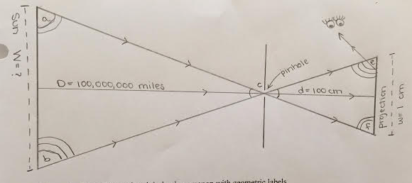
The student described this ray diagram geometrically:
(The figure above) is a ray diagram consisting of two triangles that share a point. I have labeled the vertices of each of the triangles a b c, c e f, noticing that their shared vertex is c…We can conclude that the two triangles are similar because of two different properties. The first property, vertical angles property, states that angles acb and ecf are congruent. Next, the alternate interior angles property allows us to confirm that two different sets of angles are congruent: angles abc and fec as well as angles bac and efc. The two triangles above, written acb and ecf, are similar because each of their corresponding angles is congruent. We know this because of the AAA, or Angle Angle Angle, theorem. Because these triangles are similar, we can set up a proportion…
Physics student, Spring 2016
(This student also included some numerical information on this ray diagram that refers to the activity involving pinhole cameras discussed below under section VI.)
2. Some nuances in representing pinhole phenomena geometrically
In writing about the ray diagram shown in Fig. 1.19, the student invoked several geometric ideas:
- Angles formed by two intersecting lines are called vertical angles (as occurs at the pinhole C in Fig. 1.19) and are congruent, that is, they have the same measure; if one is 30 degrees, the other also is 30 degrees.
- Some angles formed by a line (a transversal) intersecting two other lines are called alternate interior angles (such as angles a and f; also angles b and e in Fig. 1.19).
Alternate interior angles are congruent only if the two other lines are parallel. If the two other lines are not parallel, the angles will still be alternate interior angles but they will not have the same measure, that is, they will not be congruent.
- Two triangles are similar if all three corresponding angles are congruent:
Angle a is congruent with Angle f because they are alternate interior angles formed by a transveral crossing two parallel lines.
Angle b is congruent with Angle e because they are alternate interior angles formed by a transveral crossing two parallel lines.
Angle c of the big triangle is congruent with Angle c of the little triangle because they are vertical angles
- Corresponding lengths of similar triangles are proportional.
In naming the triangles “triangle acb” and “triangle ecf” this student did not follow the convention to name similar triangles so that the names of the corresponding angles are in the same position: the position of Angle a in the name “triangle acb” would correspond to the position of Angle f in name “triangle fce”; the position of Angle c in the name “triangle acb” would correspond to the position of Angle c in the name “triangle fce”; and the position of Angle b in the name “triangle acb” would correspond to the position of Angle e in the name “triangle fce”.
In referring to “angles abc and fec as well as angles bac and efc”, however, this student has followed the convention in that congruent angles a and f are in the same position, congruent angles b and e are in the same position, as are the angle c’s.
Note that this student used lower case letters, rather than capital letters, to identify angles on the ray diagram and then named each angle by listing three lower case letters with the angle letter in the middle. In this course, capital letters placed outside the vertex as in Fig. 1.18 are preferred in labeling angles of triangles such as Angle A and in naming triangles, as in the statement “Triangle ABC is similar to Triangle FEC”.
The ray diagram in Fig. 1.19 clearly represents the congruent corresponding angles in these two triangles. Note that the student has used the space between two short vertical lines to represent the pinhole as well as a ruler to make straight lines. The line with arrows drawn from the projection to the viewer’s eyes is ok in that light all the way along the projections bounces off the screen to the viewer’s eyes. However, starting this line higher, at the vertex of Angle e, would better represent rays continuously traveling from the bottom of the source straight through the pinhole to form the projection of the bottom of the light bulb near the top of the screen and then travel to the eye.
Note that the eye is shown to the left of the screen. This represents a scenario in which the student was looking at a projection on a screen where the light forming the projection reflected off an opaque screen back to the eye as in Fig. 1.21 below rather than passing through a translucent wax paper screen as in Fig. 1.15 above.
B. Representing pinhole phenomena algebraically
The visual display provided by a ray diagram also suggests describing pinhole phenomena algebraically. First, we name and label lengths as well as angles, identify ratios of corresponding lengths that are equal, and consider nuances in representing pinhole phenomena algebraically.
Question 1.15 How can you represent pinhole phenomena algebraically?
Representing pinhole phenomena algebraically requires naming aspects of pinhole phenomena that you can measure and use in a calculation. Identifying such quantities involves thinking about the variables in a situation: what, for example, affects the size of the projection that you see?
- What can you do to make the projection bigger? Smaller?
- What happens to the projection if you move the camera closer to the source? Farther from the source?
- What happens to the projection if you make the camera longer? Shorter?
- What happens to the projection if you choose a higher light source? Lower?
- Give names to those variables and draw a ray diagram that includes identifying those variables with symbols, in addition to labeling angles A, B, C, E and F.
Include, for example, a horizontal line from the middle of the vertical line representing the light source, AB, to the middle of the vertical line representing the projection to EF.
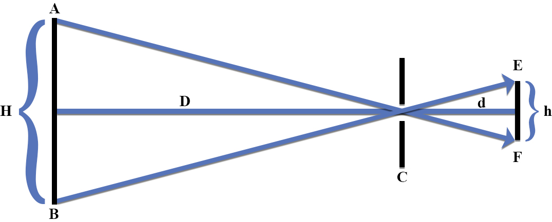
Figure 1.20, for example, includes a line representing light rays leaving the middle of the source, traveling straight through the pinhole, to form the projection of the middle of the source on the middle of the screen. This line also can represent two variables, the length, Distance D, between the light source and the pinhole, and the length, distance d, between the pinhole and the projection on the screen. The ray diagram in Fig. 1.20 also identifies H as the Height of the source AB and h as the height of the projection EF.
Note that the symbols H, D, h and d represent lengths in the two triangles whereas the symbols A, B, C, E, and F represent angles.
- How are lengths related in similar triangles?
If two triangles are similar, their corresponding lengths are proportional.
- How would you express the relationship of corresponding lengths in similar triangles algebraically with symbols?
- How would you express the algebraic relationship of corresponding lengths in similar triangles with words?
Complete writing your own response to Question 1.15 before reading an example of student work and some nuances in representing pinhole phenomena algebraically.
1. Example of student work representing pinhole phenomena algebraically
A student summarized the mathematical relationship among the lengths of similar triangles as follows:
The property of similar triangles states that triangles can be different sizes as long as they have the same shape. The same shape depends on corresponding angles and proportionate sides. In the figure we can see the relevant vertices of the triangles and proportionate sides where “H” is the height of the bulb and “d” is the distance from foil to wax paper. The Height of the bulb over the Distance from the bulb to the foil is equal to the height of the projection over the distance from the pinhole foil to the wax paper.
[latex]\begin{split} \frac{H}{D} & = \frac{h}{d} \\ \frac {\text{Height of the bulb}}{\text{Distance from the bulb to pinhole}} & = \frac{\text{height of the projection}}{\text{distance from the pinhole to the projection}} \end{split}[/latex]
Physics student, Spring 2014
This student understood the basic property of similar triangles, that they have the same shape but may be different sizes and that this means that the ratios of corresponding lengths are equal.
2. Nuances in representing pinhole phenomena algebraically
There are several aspects of representing pinhole phenomena algebraically that need attention. These include choices made in using language, naming variables, forming ratios, justifying the equal sign, deciding on an appropriate algebraic representation to use, and using one’s sense-making skills to envision and monitor what one is doing.
(a) Using language. Part of learning physics is learning to use language precisely. What words, for example, describe “H/D”? Colloquially this often is referred to as “H over D” or “height over distance”. The use of the word “over” refers to how one expresses this relationship in writing: one writes the H “over” the D. Such language can be confusing for someone who does not infer the process represented by the word ‘over’ and the line drawn between the H and D. A more precise version would be to refer to “H divided by D” or “height divided by distance”. This articulates the mathematical process involved, division. However, a more informative version would be to refer to “the ratio formed by comparing H to D” or “the ratio formed by comparing the height of something to some relevant distance, such as “the ratio formed by comparing the height of the light source to its distance from the pinhole.”
(b) Naming variables. In developing an algebraic description of a phenomenon, one has to give names and symbols to the variables that matter, in this case how high the light bulb and its projection are, and how far they each are from the pinhole. Height and Distance seem the natural names for these variables with H and D used for the height of the light source and its distance from the pinhole in the large triangle and h and d used for the height of the projection and its distance from the pinhole in the smaller triangle.
The horizontal line representing two distances here, however, would typically be described as the heights of triangle ABC and triangle FEC. Should one give a name to this variable that refers to what it is representing, distance from the pinhole, or a name to this variable that refers to its geometric role in the diagram, height of a triangle?
To avoid this confusion, sometimes we have used length to refer to the vertical lines, but the lower-case l looks like a one and L/D = l/d is also confusing. Note in Fig. 1.19, that this student had used the letters W and w to represent the width of a circular light source and its projection where use of a D and d might have been expected for representing their diameters, but D and d were already in use for representing distances from the pinhole.
The advantage of using the name height for the variables represented by the vertical lines AB and EF is that this connects the mathematical description to the objects the lines are representing, the heights of the light bulb and its projection.
An essential aspect of developing a mathematical representation of a phenomena is that after deciding on the names and symbols one wants to use, be sure to state clearly what each variable and its symbol represent.
(c) Forming ratios. When considering two similar triangles, it can be helpful to form a ratio with variables in one triangle and set this equal to a ratio formed with the corresponding variables in the other triangle. The equation with ratios that this student stated, for example, H/D = h/d, compares two lengths of the large triangle, representing the height of the light source and its distance from the pinhole, and sets this equal to a comparison of the two corresponding lengths of the small triangle, representing the height of the projection and its distance from the pinhole.
It is important to be able to express the equality of such ratios with words as well as symbols: With H/D = h/d, one is equating “how the height of the light source compares to the light source’s distance from the pinhole” with “how the height of the projection compares to the projection’s distance from the pinhole.”
One also has the choice of in what order to make such a comparison. With D/H = d/h, for example, one is equating “how the light source’s distance from the pinhole compares to the light source’s height” with “how the projection’s distance from the pinhole compares to the projection’s height.”
In both cases, this approach has the advantage that the units used within the same triangle will match. In this case of comparing one length to another length, with both lengths measured in the same units, the ratios will be dimensionless. This means that, if convenient, one can use units for the lengths in the large triangle that differ from the units for the lengths in the small triangle.
Sometimes, however, one might want to compare the same variable in the two triangles, setting the ratio of the heights, for example, equal to the ratio of the distances: H/h = D/d In this case, one is setting equal “how the light source’s height compares to the projection’s height” with “how the light source’s distance from the pinhole compares to the projection’s distance from the pinhole.” One also could set this equation up as: h/H = d/D. Here one is setting equal “how the projection’s height compares to the light source’s height” with “how the distance of the projection from the pinhole compares to the distance of the light source from the pinhole.”
Although cumbersome, keeping in mind the word description of what these ratios represent can prevent randomly setting up an equation that may look appropriate: h/D = H/d but is not justified in this context.
(d) Justifying the equal sign. When setting one algebraic expression equal to another in this course, it is important to justify the equal sign explicitly. For example, one student wrote:
In the figure, there are two triangles seen, triangle ABC and triangle FCE. The two triangles are similar because they have three sets of congruent angles. The first set of congruent angles are vertical angles, in which Angle ACB ≈ Angle FCE. The second set of congruent angles are alternate interior angles, in which Angle CAB ≈ Angle CFE.
The third set of congruent angles are alternate interior angles, in which Angle CBA ≈ Angle CEF.
Since the two triangles have congruent angles, they are therefore similar triangles because of the AAA theorem. The corresponding sides of similar triangles are proportional, which is why we are able to set up a proportion comparing the two triangles.
Physics student, Spring 2016
Note that this student has not used the convention in naming the triangles. Triangle ABC puts angle C in the third position but Triangle FCE puts angle C in the second position. An alternative would be Triangle ABC is similar to Triangle FEC or Triangle ACB is similar to Triangle FCE. The student has used the conventions in naming angles so that the angle of interest is the middle letter: Angle ACB and Angle FCE are both referring to the angle where the two lines cross at C. Angle CAB refers to the angle at A and Angle CFE refers to the angle at F, a set of alternate interior angles at A and F. Angle CBA refers to the angle at B and Angle CEF refers to the angle at E, the other set of alternate interior angles.
(e) Choosing an appropriate algebraic representation. If H/D = h/d, D/H = d/h, H/h = D/d and h/H = d/D, which set of equal ratios should one use?
If you can measure three of the variables and need to calculate the forth, any of these will work. However, some are easier to use than others.
Solving for an unknown that is in the numerator for many students is easier than solving for an unknown in the denominator. If asked to find the height of a projection, h, for example, choose a version with h in the numerator: H/D = h/d or h/H = d/D . Then isolate h by multiplying both sides by the variable in the denominator:
[latex]h = d\,(\frac{H}{D})[/latex] or [latex]h = H\,(\frac{d}{D})[/latex]
Note: Avoid using x to represent multiplication in an algebraic equation as this can be misinterpreted as representing an unknown. Use parentheses or a dot:
[latex]h = H \,\bullet\, \frac{d}{D}[/latex] to represent multiplication.
f) Using sense-making skills to envision what an equation is doing. People in this course typically differ in their experiences and comfort in setting up and solving algebraic equations. If you are feeling some anxiety after reading this section, it is important to give yourself time to connect each symbol with what it means, not only by writing out its definition and labeling it on your ray diagram but also by visualizing what the symbol represents within an equation.
When solving a pinhole problem, for example, write h = height of the projection and place an h next to the vertical line representing the projection on your ray diagram; then step back and visualize the size of the upside down projection you saw on the wax paper screen of the pinhole camera. Do the same for the d, H, and D.
The goal is to become familiar enough with the symbols that when you see H/D = h/d, your mind visualizes what those ratios mean:
- you can “see a comparison in your head of the big Height of the light bulb with the big Distance from the light bulb to the pinhole of your pinhole camera;
- you can “see” a comparison in your head of the little height of the projection with the little distance from the pinhole to the wax paper screen of the pinhole camera;
- and you can “see” that those comparisons seem about equal;
- that, for example, the big Height of the light bulb is about a tenth of the size of the big Distance from the light bulb to the pinhole in the pinhole camera in your hand
- and that the little height of the upside down light bulb projection seems about a tenth of the size of the little distance from the pinhole in the aluminum foil end of the tube to the wax paper screen.
Also use words to tell yourself a story about what the equation is doing, that the equation is comparing heights to distances in two similar triangles and if the triangles are similar, the comparisons of heights to distances are equal even when the sizes of the triangles are very different. Visualizing what the equation is doing is key to clarifying in your mind whether you have set up the equation in a way that makes sense.
(g) Using sense-making skills to monitor what one is doing. In addition to visualizing what an equation is doing, it is important to use sense-making skills to monitor what you and your group members are doing. In solving a complex problem, it is easy to get focused on some detail that in the end is not needed. To make productive progress, it is important to step back for a moment to ponder:
- What are we doing?
- Why are we doing that?
- How will that help us?*
This is particularly important to do periodically when engaged in a multi-step endeavor, such as designing an experiment, collecting data, and using the data and one’s knowledge of physical phenomena to estimate a quantity that can not be directly measured such as the diameter of the Sun.
*These questions are suggested by Alan Schoenfeld (1992) as meta-cognitive checks when engaged in problem-solving.
Schoenfeld, A. (1992). Learning to think mathematically: Problem solving, metacognition, and sense-making in mathematics. In D. Grouws (Ed.), Handbook for Research on Mathematics Teaching and Learning (pp. 334-370). New York: MacMillan
(h) Using one's knowledge of geometrical and algebraic representations of pinhole phenomena to explore ways to estimate quantities one wants to know. Suppose you want to know, for example, how high something is, like a tree. How would you use a pinhole device to find that out? What would you need to measure and do if you used the equation H/D = h/d ? You can practice such approaches in a dark room by using data from your exploration of variables affecting pinhole phenomena (Question 1.12). What would you need to measure if you wanted to estimate the height of the lightbulb? If H = D(h/d) and you substitute your measurements in this equation, how does your estimate compare with an actual measurement of the height of the bulb?

